
Infineon announced HybridPACK HD on November 18, naming a module for traction inverters in electric trucks, buses and other commercial vehicles. The company quotes an output current range of 500 to 1,200 amperes RMS and says the first listed part, FF01MR14A60MA2XT, is available. It uses 1,400-volt silicon carbide MOSFETs and a directly liquid-cooled package. The announcement is useful because it makes a high-current component available for evaluation. Its practical consequence depends on the current and temperature an entire inverter can sustain in a vehicle, the conditions in which it was qualified and how much work a fleet expects it to do. Infineon’s announcement · The part and its specifications
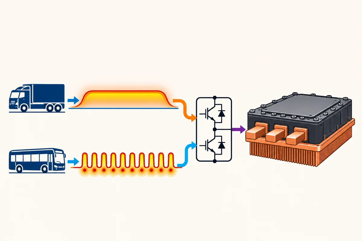
A truck that spends hours on a motorway and a city bus that starts and stops all day can show the same number on an odometer. They can put different loads on their inverters. The bus may accumulate more changes in current and heat over that distance. The truck may spend longer under sustained load on a grade. The energy cost, cooling demand and time available to repair the vehicle also differ. Those distinctions explain why a package aimed at commercial service can be worth developing. The operator is buying predictable work across a route, a season and many years of use.
The final datasheet already gives an electrical part number and a set of test conditions. Independent electronics coverage distinguishes those data from the supplier’s broader launch claims. That is where the product can be assessed. The current through one switch, the current at the output of an inverter, the rating of an insulation feature and the limit of a charging interface describe different points in a system. A single large number cannot stand in for all of them. Final datasheet · IN Electronics & Design’s coverage
Three currents serve different purposes#
HybridPACK HD packages a silicon carbide half-bridge. A traction inverter switches energy from the battery’s DC supply to the motor’s phases and can route energy back during regenerative braking when the vehicle allows it. A half-bridge supplies one element of that conversion. The part’s switches, connections and baseplate come together inside the package. The vehicle manufacturer still integrates control, cooling, sensing, protective functions and the rest of the electrical system. That gives the module an important job whose contribution can be measured without assuming it sets every vehicle limit. Infineon’s part description and circuit · Datasheet
The announcement puts output current at 500 to 1,200 amperes RMS. RMS describes the effective magnitude of a varying current. The datasheet for the named product separately lists 850 amperes as implemented drain current, a stated continuous DC drain current of 785 amperes under specified thermal and electrical conditions, and a repetitive peak drain current of 1,700 amperes limited by junction temperature and pulse duration. These are different figures for different measurements. A buyer cannot read the peak number as sustained operation. It needs the duration, waveform and environment attached to the result it wants to compare. Announcement current range · Datasheet limits, table 3
One consequence is that the inverter has several operating points of interest. A short demand when pulling away from a stop may be bounded by a different condition from sustained work on a climb. The cooling fluid can start the shift warm or cold. The motor and transmission can ask for a different combination of speed and torque at the same output power. A useful test report shows which part of that range was exercised and whether output changed over time. A short peak can matter for acceleration, while a long stable interval may determine what a haulier can do on a particular route.
Infineon argues that the package can simplify some high-current designs by reducing the need to connect multiple power modules in parallel. That can reduce the number of packages, connections and tasks around matching current between them. It can also concentrate heat and make each connection important to the result. The buyer needs to know where the proposed assembly saves cost, which parts it still requires and how a module failure is handled. One fewer set of components can help an inverter fit within a limited enclosure. It does not by itself show how the system performs under repeated load. Infineon’s design rationale
Consider two test vehicles that reach the same peak output. One can run near that level for a steep part of the route and cool steadily afterward. The other may reach it several times and reduce output as temperatures rise. The first journey and the second place different demands on the driver and the operator. For a supplier’s specification to inform that decision, it helps to give performance across the relevant parts of each trip, including the time to recover. Referencing a module’s RMS range is a useful starting point after the operating conditions have been written down.
The package has to carry heat and vibration#
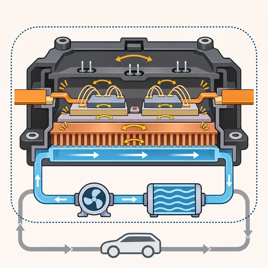
The module uses Infineon’s .XT interconnection technology and a PinFin baseplate for direct liquid cooling. Its final datasheet also describes an integrated temperature sensor. The package is consequently more than the chip’s switching properties. Its joining layers, connections and thermal path help determine how reliably heat reaches the coolant and how the assembly responds when loads change. Silicon carbide can contribute to efficient conversion under suitable conditions. The buyer still needs to evaluate the connections and cooling that will help the assembled inverter reach those conditions. Datasheet on construction and cooling · Manufacturer’s application note
In service, electrical losses cause a device to heat up. Different materials expand and shrink by different amounts. A commercial route can repeat these changes many times. Their magnitude, timing and average temperature affect which parts see fatigue. Infineon names sintered die attachments and copper bond wires among the package’s joining features. That is evidence of a construction choice aimed at reliability. A comparison can examine tests of interconnections after repeated cycles and how closely the tests reflect the planned route and cooling system. Product description · ECPE’s qualification guidance
A published thermal resistance is tied to a measurement boundary. In the datasheet, the path from the junction to the cooling fluid is characterised for specified fluid and flow conditions. A completed vehicle adds pumps, heat exchange, control and other cooling demands. A lower resistance in the module can make the heat easier to move. The vehicle engineering team has to verify the flow, temperatures and duration it can actually maintain. A buyer comparing modules can then tell whether a thermal advantage is likely to survive the final layout, including periods of high road load. Thermal characteristic conditions
Bench and vehicle measurements can meet at a specific operating point. An engineer can record coolant temperature and the inverter’s losses during the same stretch of work, then see whether the vehicle continues to cool the part as the load persists. Comparing a late hot section with the start of a cold test answers a different question from measuring the steady interval on both drives. A production buyer can request both readings and the relevant software version. That makes it easier to distinguish a characteristic of the module from the response of the vehicle’s cooling controls.
Vibration is another recurring condition. The official data lists qualification according to ISO 16750-3 for vibration, alongside its automotive power module and attachment qualifications. A vehicle designer still has to account for how the mounted assembly moves, where the unit sits in the drivetrain and what its connections experience when the truck is carrying a load. A tested module supports that work with a defined reference. The position and mounting in a complete vehicle can require a separate assessment. Datasheet on qualifications and mechanical conditions
Cooling and serviceability can be linked. A fleet workshop cares about what it must remove to inspect or change a failed part, how long a repair takes and what checks follow. If the inverter shares other systems, diagnosing a temperature anomaly can involve more than the power module. A design that keeps selected components accessible may reduce time spent on each repair. One that reduces the need for repair may matter more on routes far from a workshop. A credible service comparison says what work was actually required, along with the conditions that caused it.
More than a million kilometres is a design claim#
Infineon’s launch release describes a design lifetime requirement above 1.2 million kilometres. Its part page separately describes a lifetime above 1.5 million kilometres in discussing the interconnection technology. The public information does not supply the common route, vehicle, loading conditions and method needed to compare those two figures as results. The announcement discusses operating lives of more than 80,000 hours as a heavy-duty challenge. That is a description of the market’s needs. The module does not come with a demonstrated record of every truck completing one of those missions. Infineon launch release · Part page · VLSI’s reading of the two figures
Distance and service time need an explicit relationship. A hypothetical vehicle averaging 40 kilometres an hour during the hours counted as movement would cover 1.2 million kilometres in 30,000 such hours. A vehicle averaging 20 would need twice those hours. Neither calculation measures the product or says which hours should be counted towards a right to service. A bus can sit with systems on while waiting at a depot. A tractor can travel far in one steady interval. The numbers show why distance, time, switching activity and temperature history need to be stated together when comparing lifetime.
ECPE describes AQG 324 as a common procedure for characterisation, environmental and lifetime tests on automotive power modules. The Infineon datasheet identifies the revision for this module. Such evidence makes standardised comparison possible. A qualified component still needs to meet the particular mechanical and electrical loads in a vehicle. A useful manufacturer account can explain how its assumptions map to a route profile and whether the validation includes sustained power, time at temperature and changes over the service life. A defined module test lets buyers ask which additional results the vehicle team has obtained. ECPE’s description of AQG 324 · Module validation statement
A fleet looking at reliability also needs to know what ends the life of a part. Loss of all operation, a change in performance that triggers replacement and a repair required during normal maintenance can be counted in different ways. The conditions for warranty and the pattern of failures across many vehicles can be more useful than the longest interval one demonstrator has achieved. Calls to recover a bus or truck cost money every time. Reported availability and the reasons for lost hours put the part’s design target in the context of paid work.
There can be an early and a late signal of reliability. Component screening can catch defects before installation. Development tests can reveal how a material or connection responds over repeated cycles. Fleet use can expose distribution of loads or maintenance decisions that an accelerated test did not reproduce. These are complementary forms of evidence. If a supplier changes a material or production site, later records can show whether it confirmed the same lifetime assumptions and communicated the change to the buyer. The point is to follow the part as manufactured and installed.
A traction module and a charging interface use different voltage figures#
The available part’s datasheet identifies 1,400 volts as the maximum specified drain-to-source voltage under its stated junction temperature conditions. On the product page, the 1,500-volt DC language appears in a feature describing creepage and clearance, the distances that help separate electrical conductors. The announcement talks more broadly about future high-voltage battery architectures. The module’s semiconductor limit still applies. A vehicle team has to verify the voltage and transients each switch actually sees, the inverter architecture and the applicable margins. The public material does not establish that this half-bridge can sit across an arbitrary 1,500-volt bus. Datasheet electrical limits · Product page on isolation spacing
This distinction matters even for someone who never designs a circuit. A system label can describe the battery architecture, a mechanical insulation boundary or a maximum operating point of one component. The labels can be close enough to be confused. Engineering checks separate these points and include the voltages that appear temporarily when a load changes. A high-voltage layout also brings requirements for other components, protection, connectors and maintenance procedures. Buying one rated component establishes a bounded option for the design. It does not transfer the number to the whole system.
Megawatt charging has its own boundaries. CharIN’s account of IEC 61851-23-3 describes an MCS supply equipment specification with up to 1,500 volts DC on the equipment supply side and a maximum of 1,250 volts DC on the vehicle side. It also identifies standards for the connector, communication and vehicle power transfer. These limits are for the relevant roles in a charging system. A power module in a vehicle’s traction inverter, a battery and a charger’s feed each do a different job. A module announcement does not establish that the complete vehicle matches a particular charger. CharIN on the MCS standards framework
Higher bus voltage can lower current for a given power in a suitable system. In a simplified example of 500 kilowatts of DC electrical power, the corresponding current would be 625 amperes at 800 volts or 500 amperes at 1,000 volts before losses and without assigning either condition to the Infineon module. The comparison concerns DC power. A motor phase waveform and a charging cable current cannot be inferred from it. This is why a driver’s charging wait, a fleet’s depot costs and a vehicle’s traction capability need separate measurements.
Available charge power on a route depends on the battery’s permitted charging conditions, the connector and communications, the station’s electrical service and what other vehicles are using. A vehicle may accept its peak rate briefly or reduce it as state of charge and temperature change. A depot may distribute a limited supply across several trucks over a longer scheduled pause. Infineon’s positioning gives manufacturers a component to consider for high-voltage platforms. An operating plan should still use the vehicle’s charging curve and the station’s conditions to estimate time. Published deployments such as Scania’s MCS effort concern their own equipment and make no claim about this Infineon part. Scania MCS announcement via CharIN · Infineon product positioning
The cost that matters is cost per available vehicle#
Infineon presents the package as a route to lower total cost of ownership. A vehicle maker might save on the number of modules and connections, or on assembly time and the size of a cooling system. A fleet might gain if the inverter uses less energy in its common operating region or keeps vehicles available for more scheduled trips. Those costs belong to different buyers. They can arrive at different times. One attractive unit price does not give the fleet a reduction if later repair or electricity costs are higher. Infineon on intended cost benefits
In a simple fictional comparison, saving 0.03 kilowatt-hours per kilometre across 120,000 kilometres a year would reduce energy use by 3,600 kilowatt-hours. At an assumed $0.14 per kilowatt-hour that would be $504 a year before demand charges or differences in charging and maintenance. These are invented inputs to show how an efficiency claim becomes a budget line. They are not measured HybridPACK HD performance. If a fleet uses a different route, price or utilisation, the financial result moves with it. The measurement that matters is the change on the same job under comparable conditions.
A repair record can tell another side of the story. Consider a route with a limited choice of spare vehicles. A failure during service can require a tow, a substitute and several hours of time. The same part replaced during scheduled maintenance can have a much smaller impact. A design target for power cycling can help reduce one source of failures. Access to a part and a trained workshop can reduce recovery time when a failure occurs. Both deserve a place in the budget. They are evaluated through different records, including downtime and the outcome of each intervention.
The records also need comparable denominators. A larger fleet may report more workshop visits even when the failure rate per vehicle-hour falls. A change in preventive maintenance can move an intervention from the road to the depot, reducing lost trips even if replacement counts are unchanged. A publication that includes vehicle-hours, route type and the timing of a repair makes these changes visible. A fleet can then decide whether an improvement served reliability, repairability or both. The estimate is useful only for the work and exposure represented in the records.
A manufacturer can also look at how the module affects the family of vehicles it can build. A consistent envelope across several duties can reduce the expense of maintaining variants. A city bus may benefit from retaining a modest, predictable package. A higher-power application may justify a change to the cooling system or electrical enclosure. A buyer can compare how many parts and tests are reused across programmes, what must be checked again and whether sourcing supports the full product life. The announced family range offers options. The customer still chooses a documented configuration for each vehicle.
Availability opens the next round of qualification#
Infineon identifies the first named part as available. The datasheet revision predates the launch announcement. A distributor also listed a module description before the formal release. The timing shows that the announcement publicises a component and its intended use. Selection by an automaker, delivery of production quantities and operation in a fleet are separate events. The public materials do not identify an installed fleet or establish orders for a particular vehicle programme. An available part lets teams start work on those decisions. Infineon’s availability statement · Dated final datasheet
The next evidence has several levels. A component evaluation can show how the supplier meets its ratings. An inverter test can record the duty cycle, cooling conditions and electrical performance in the finished unit. A vehicle validation can set out work on a known route at an agreed load, and later service records can show what changed after months or years in use. These stages give the buyer progressively closer evidence. No one test has to be stretched from an electrical limit into all of the answers a commercial operator needs.
The purchase also needs a delivery commitment. A prototype team may need a few parts now. A fleet vehicle programme can need a regular schedule, the ability to replace a variant and notice if a process evolves. The partner has to supply the pieces that the vehicle manufacturer qualified. Publication of capacity is useful if it connects to the specific package and delivery dates. A vehicle maker can also ask how an engineering change would affect existing parts and service inventory. The choice of semiconductor module includes these ordinary procurement conditions.
HybridPACK HD offers a defined part for a demanding job. The strongest evidence for it will join the electrical limits to an inverter and the inverter to real work. A buyer can then see how long a loaded truck or bus can operate, what heat and vibration the package experiences, how the inverter is maintained and what the complete vehicle does at a compatible charger. The datasheet makes several of those questions possible to ask now. The product’s value will show in the answers manufacturers and fleets can record.